Tuesday, December 14, 2010

Our Chair is ready To Output

rendering of chair: Exploits both waffling and stacked contouring
Using Grasshopper to generate surfaces for the seat and base, we baked it into rhino.  In rhino we offset the surfaces and contoured them.  From this model we were able to create a laser cut file in cad.  After laying out the pieces we model them to check for continuity and any discrepancies.  Here are a few snap shots of what the final chair should look like, however we have made some slight modifications as to how the edge of the seat will look (no exposed rib ends).

Tomorrow we are outputting our chair at 1/2 scale.  It will roughly measure 15 inches tall.  It will be constructed out of 1/4" MDF and cut using the lasercutter.

Chair Rendering: Note the language of bent planes, one clearly defining the base and the other clearly defining the seat.

Sunday, December 12, 2010

Using Formulas to Generate a Base for Our Seat surface

Screenshot: Seat with Base
If cosine lends itself for deriving a desired seat section could a similar formula lend itself to creating a seat base?  We asked ourselves this question hoping to find an equation that could possible play the role of both seated surface and as a support.  After reverting back to high school algebra II/trig we were reminded that formulas with Asymptotes were similar to the section of our seat base.

Several attempts to finding a formula that would be appropriate for representing the points that defined our seat base brought us to polynomial functions.


A quartic function (x^4) has the right number of degrees necessary for providing the section we needed.  We once again used this formula with number sliders attached to the variables associated with this function to the derive the base height and width. 

Screenshot: Entire Script
Screenshot: Seat base Script

Now that we have a seat base using the x^4 function and a seat surface using a CosX function, it is important that these two surface will be able to intersect in a manner that will allow them to share curvature.   Our next step is to go into the Seat portion of our script and replace it with the X^4 function so that the two separate surface will have the same curvature at the place where they overlap.

Once we have successful achieved this we should be able to output this chair at 1/2 scale and then finally at 1:1.

Aligning Sections to Normals

In tour previous script version our cross-sections were not aligned to the normals of the seat profile section.  We were able to go into our exiting script and rotate the frames based on their relative angles.

Screen shot: Entire Script
Rotating the curves to normals

more editing of seat surface

Elevation showing the frames rotated to normals


Rotating each plane normal to the curve of the  section makes the shape of the seat surface smooth and minimizes irregular geometries when baking out form into rhino.

Outputting our first Prototype

Screenshot:  Rhino, Contoured surface

Lasercut file
Can the CNC become a frame or Armature?

What are the least amount of material needed?

fully assembled chair


Cardboard Chiar @ 1/4 scale

Appling An Equation to the Seat Cross Sections

Screenshot: Entire Script
Our next attempt utilizes a simple Cos(X) function to generate the cross section of the seat. Using the cosine function allows us to adjust the contour of the seat more rapidly than before, where we had to adjust each control point with an individual slider. With the cosine function we are able to adjust multiple points along a curve at once.


Screenshot: Start, Divides seat section into 8 nodes, places a frame and provides start point for each section curve
 When the cosine equations are created they automatically want to start at the origin in Rhino.  To relocate them to a specific start point we created a spline that represented our desired seat cross section in profile.  We then divided that spline into seven parts and placed a frame at these divisions.  extracting the x,y,z value at these intersections we were able to assign this as the origin for each equation, giving us an adjustable cosine curve at seven locations along the section of our chair.
Screenshot: Middle, Cosine equation Parameters, allows editing of curvature
 By editing the Amplitude, period and frequency of the COSX function, we are able to generate different seat depths and widths.  Seven of these functions are employed across the entire seat.  Variation to each equation changes the character of the chair from seat back to seat.


Screenshot: End, lofts curves and mirrors them to make the complete chair.
To generate a surface from this data we then take the curves generated from the Cos(x) function and loft them.  Because these curves only represent half of the chair we then mirror this surface to create a complete and symmetrical seat.

Screenshot: Seat with Seatback derived from 7 sections

This is what the seat looks like based on the script we have written.  Not bad.  You can already begin to see the making for a seat and a seat back.

We then begin to tweak the sliders associated with the cosine function and you can see how we are able to drive formal responses.  We will now be able to use rhino to help out put our first prototype.
Screenshot:  Editing Varibles for seat section Equation

Looking For a Better Solution

Gerard Petersen's Boat Hull Script
Looking through tutorials one day I stumbled upon a set of videos on Youtube demonstrating the use of Grasshopper to generate boat hulls.  The video demonstrated the use of parametric definitions to create a ships hull that is adjustable based on keel depth, displacement, and  stern vs. bow proportions.  I contacted the author of the video, Gerard Petersen, to get more information about how he structured his script for the boat.  He was kind enough to email us this script.  Max and I spent several hours examining and trying to make sense of this very complex script.  What we discover is that Gerard used an equation to define each specific cross section at certain intervals along the boats hull.  Then by assigning a number slider/inputs to the variables associated to each equation he is able to generate a parametric form that is very fluid and editable based on specific numerical input.

Gerard Petersen's Youtube Video

You can view this video @ http://www.youtube.com/watch?v=lbV9MllyP8I&feature=related

First Explorations with GrassHopper

Screenshot: Entire script

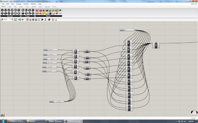
Our first attempts with Grasshopper have been successful for the most part.  We have written a script that generates 6 points along the section of the seat.  These points are then copied along the length of the seat and mirrored(to maintain symmetry about the seat) creating a total of 12 points.  Each point's Z position can be edited by using a number slider.  Since all of these points are used to generate curve we can then use these curves to create a surface by lofting.  The end result was a seat surface.

The down side to this script is that it is really no different from just creating a nurb surface in Rhino and then editing each control point individually.  To refine the perfect curvature for this seat will take way to long to edit.  We are going to have to find a better way to make editing the seat curvature more fluid and responsive. 

Screenshot: Seat sections portion of the Script

Screenshot:  Point Isolated
Screenshot:  Exaggeration of editing one point along curve

More Sketching....


The above sketches are Max's exploration of a possible aesthetic for the chair based on  several constraints.  Since we are planning on outputting this chair on the CnC or Lasercutter, we are aware of a certain tectonic that is inherent of this process.  Dissatisfied with most chairs that are output on CnC/lasercutters, generally being waffle grids, we wanted to try and find a language that begins to move away from this construction technique. 

We are starting to discover that by creating a hierarchy of waffled pieces, larger for structure, smaller for infill, it begins to break down the redundancy of the waffling technique.